In this project, we will build a water level control system using an ESP8266 NodeMCU and a waterproof ultrasonic sensor. We can monitor the water level on the Blynk dashboard.
A smart, automated method for managing and maintaining water levels in many applications, such as tanks, reservoirs, and swimming pools, is an Internet of Things (IoT) water level management system. These systems gather and analyze data via IoT devices, sensors, and cloud-based platforms. This data is used to provide real-time monitoring of water levels, optimize water consumption, and prevent waste.
This project effectively handles the problem of water wastage and maintains optimal water levels. The system manages all electronic components and conducts actions depending on the WiFi network connection using the ESP8266 WiFi Module as the principal controller. Water levels are measured via the JSN-SR04T ultrasonic sensor, which is positioned at the top of the tank. These water levels are shown on a 0.96′′ I2C OLED panel for simple monitoring.
The device may operate in either manual or automated mode, with a relay in the circuit controlling the on/off status of the water pump. The Blynk application allows users to observe and manage the water level and mode control functions, guaranteeing effective water usage and conservation.
Parts List
You will need the following items to proceed with this project:
- ESP8266
- JSN-SR04T Ultrasonic Sensor
- 0.96″ I2C OLED Display
- Hi-Link 220V AC to 5V DC Converter
- 5V Relay Module
- Push Button Switch
- AC Water Pump
- Pipes 2 meters or more
- Zero PCB Board
The ESP8266 NodeMCU WiFi Module serves as the primary controller in this project. The ultrasonic sensor HC-SR04 may be used to detect the tank's water level. However, the JSN-SR04T Waterproof Ultrasonic Sensor is a better choice in this instance.
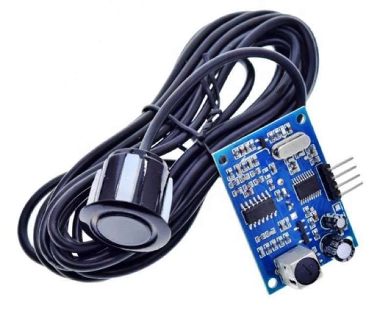
The JSN-SR04T is a waterproof variant of the famous HC-SR04 ultrasonic distance sensor. It is intended for use in tougher environments where water or moisture may be present. The module determines the distance to an item using ultrasonic sound waves by producing a sound wave and then measuring the time it takes for the echo to return.
A 0.96′′ SSD1306 OLED display may be used to display the water level. The SSD1306 0.96′′ OLED Display is a popular and small display module that is used in a variety of DIY electronics projects. It is built around the SSD1306 driver chip, which is intended to power monochrome OLED displays.
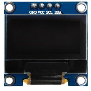
The display has a resolution of 128×64 pixels and produces a sharp, high-contrast image, making it suitable for showing text, graphics, and icons, among other things. Typically, the module interacts using the I2C (Inter-Integrated Circuit) protocol with microcontrollers such as the Arduino, ESP8266, or Raspberry Pi.
We used the HLK-PM01 AC to 5V DC converter module for supplying power and regulating the relay. The Hi-Link AC to 5V DC converter is a small and efficient power supply module that converts alternating current (AC) mains voltage (typically 90V–264V AC) to a stable 5V DC output.
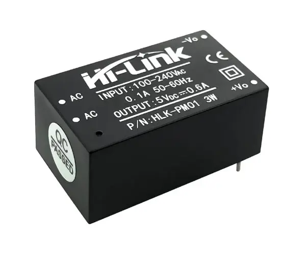
These modules are widely used in a variety of electronics and Internet of Things projects that require a 5V DC supply from the main power source.
Circuit Design & Connection
The IoT-based Water Level Control and Monitoring System circuit constructed using a waterproof ultrasonic sensor and an ESP8266 NodeMCU board is shown below.
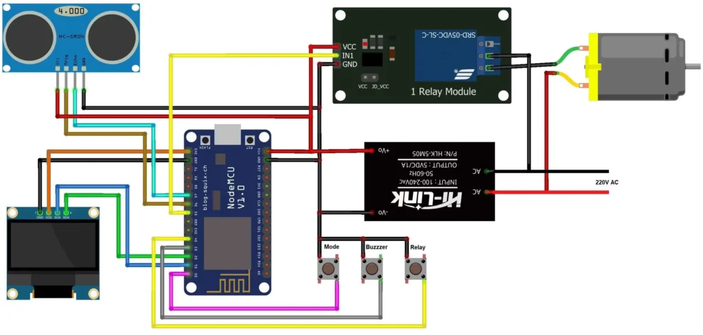
There are four pins on the waterproof ultrasonic sensor. The ESP8266's D7 and D6 pins are connected to the ECHO and TRIG pins. It is powered by the ESP8266 at 5V. Because the OLED Display is an I2C Module, its I2C pins SDA and SCL are connected to D2 and D1 of the ESP8266 NodeMCU, respectively.
This project makes use of three push buttons. They are used for mode selection, buzzer operation, and relay operation. The push buttons are connected to the D0, D3, and D4 pins.
The HLK-PM01 AC to 5V DC converter module may be used for the supply unit. The 220V AC is fed as input, and the 5V DC output is fed to the ESP8266's Vin pin. The relay is controlled by the ESP8266's digital pin D5. The relay is essential for controlling the AC motor pump. When the relay turns on, the motor turns on as well, and when it turns off, the motor turns off.
I used Zero PCB to assemble the circuit. All components fit perfectly on the board.
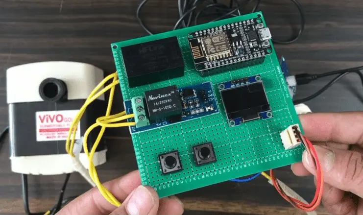
Because I am not using the buzzer on my board, I am only using two push buttons for my project. A push button may be used to trigger a buzzer on the PCB.
The ultrasonic sensor may be placed on top of the tank, while the motor can be placed within. I used two buckets in my project. The motor pulls water from a water source into one bucket, which functions as a tank.
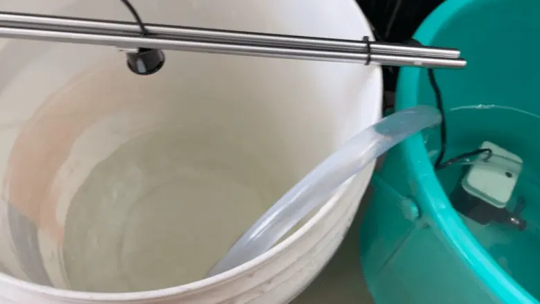
You may use any AC water pump or just a 12V output pump and connect it to the output terminal of the relay.
Setting up Blynk 2.0 Application
To create a Blynk project and set up a dashboard on the mobile or web application, you need to monitor and control the water level. This is how you set up the dashboard:
1) On the Blynk website, go to blynk.cloud and create a Blynk account. You can also sign in using your registered email address.
2) Select “New Template“. Then give the hardware whatever name you choose. Select ESP8266 as the hardware type and WiFi as the connection type. The template was successfully created.
3) Now we need to add new devices here.
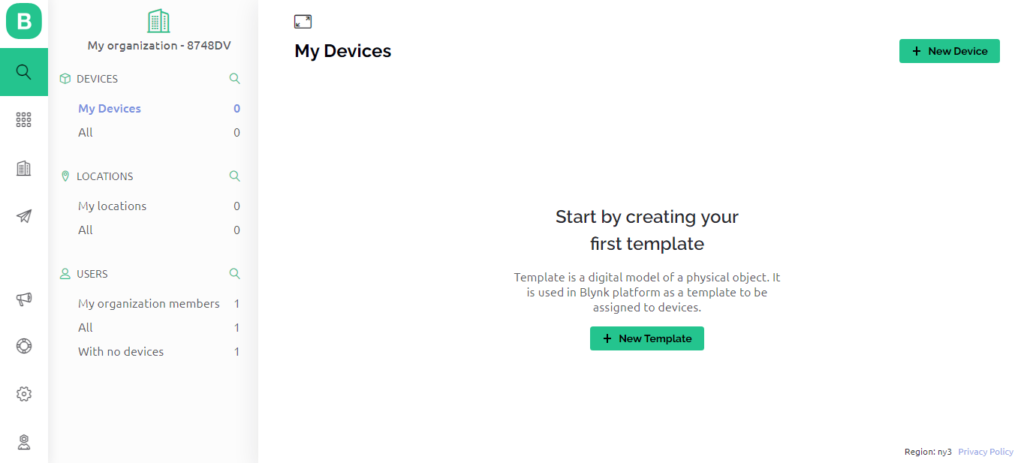
4) Choose a device from the template you created before. Give it whatever name you choose, and then click Create. A device authentication token is being generated right now. This token must be copied since it will be used in the code.
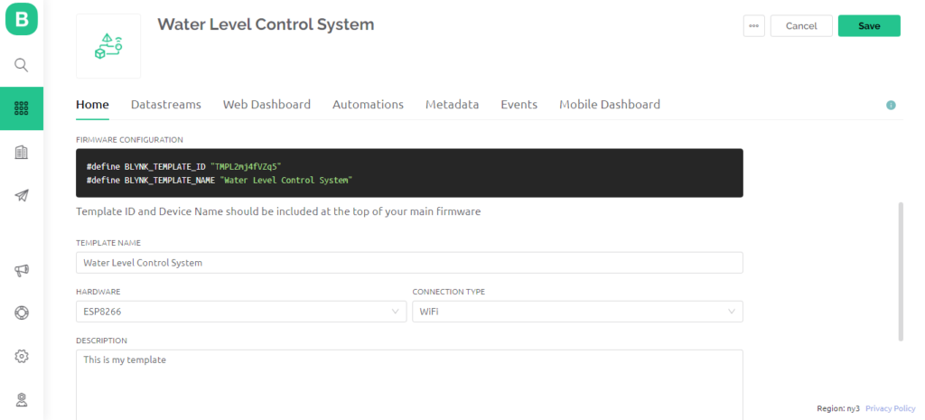
5) Now go to the Web Dashboard. Drag and drop three widgets as gauges and two switches onto the dashboard in the Web Dashboard. The dashboard should then be set up as seen in the following screenshots:
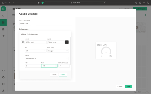
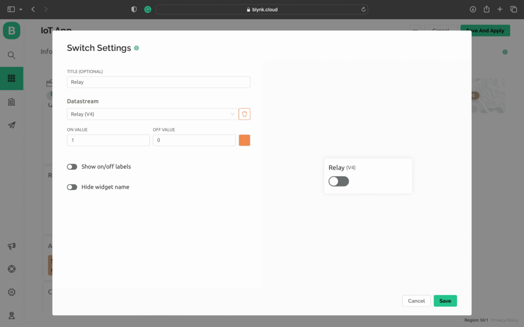
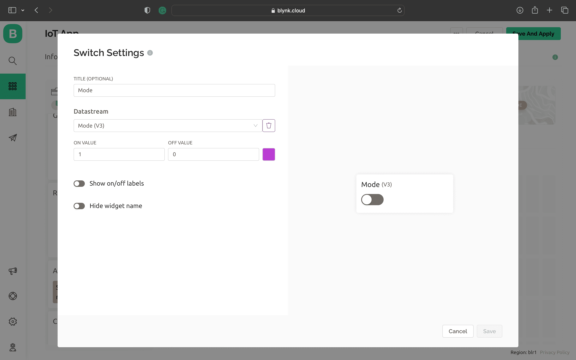
The Blynk Dashboard setup is now completed.
Source Code/Program
The following is the complete code for a water level control and monitoring system using the ESP8266. The code is written in the Arduino IDE.
There are a few changes that you need to make before uploading this code to the ESP8266 board.
In the following lines, change the Blynk authentication token.
#define BLYNK_TEMPLATE_ID "***************"
#define BLYNK_TEMPLATE_NAME "**********************"
#define BLYNK_AUTH_TOKEN "*************************"
Replace the WiFi SSID and password in the following lines:
char ssid[] = "****************";
char pass[] = "**************";
After making these changes, you can now upload the code to the ESP8266 board.
#include <Adafruit_SSD1306.h>
#include <ESP8266WiFi.h>
#include <BlynkSimpleEsp8266.h>
#include <AceButton.h>

#define BLYNK_TEMPLATE_ID "***************"
#define BLYNK_TEMPLATE_NAME "**********************"
#define BLYNK_AUTH_TOKEN "*************************"

char ssid[] = "****************";
char pass[] = "**************";

int emptyTankDistance = 160;
int fullTankDistance = 20;
int triggerPer = 20;

using namespace ace_button;

#define TRIG 12                //D6
#define ECHO 13                //D7
#define Relay 14           //D5
#define BP1 2              //D0
#define BP2 13             //D3
#define BP3 15             //D4

#define V_B_1 V1
#define V_B_3 V3
#define V_B_4 V4

#define SCREEN_WIDTH 128
#define SCREEN_HEIGHT 32

#define OLED_RESET -1
Adafruit_SSD1306 display(SCREEN_WIDTH, SCREEN_HEIGHT, &Wire, OLED_RESET);

float duration;
float distance;
int waterLevelPer;

bool toggleRelay = false;
bool modeFlag = true;
String currMode;

char auth[] = BLYNK_AUTH_TOKEN;

ButtonConfig config1;
AceButton button1(&config1);
ButtonConfig config2;
AceButton button2(&config2);
ButtonConfig config3;
AceButton button3(&config3);

void handleEvent1(AceButton*, uint8_t, uint8_t);
void handleEvent2(AceButton*, uint8_t, uint8_t);
void handleEvent3(AceButton*, uint8_t, uint8_t);

BlynkTimer timer;

void checkBlynkStatus() {

  bool isconnected = Blynk.connected();
  if (isconnected == false) {
  }
  if (isconnected == true) {
  }
}

BLYNK_WRITE(VPIN_BUTTON_3) {
  modeFlag = param.asInt();
  if (!modeFlag && toggleRelay) {
    digitalWrite(Relay, LOW);
    toggleRelay = false;
  }
  currMode = modeFlag ? "AUTO" : "MANUAL";
}

BLYNK_WRITE(VPIN_BUTTON_4) {
  if (!modeFlag) {
    toggleRelay = param.asInt();
    digitalWrite(Relay, toggleRelay);
  } else {
    Blynk.virtualWrite(V_B_4, toggleRelay);
  }
}

BLYNK_CONNECTED() {
  Blynk.syncVirtual(V_B_1);
  Blynk.virtualWrite(V_B_3, modeFlag);
  Blynk.virtualWrite(V_B_4, toggleRelay);
}

void displayData() {
  display.clearDisplay();
  display.setTextSize(3);
  display.setCursor(30, 0);
  display.print(waterLevelPer);
  display.print(" ");
  display.print("%");
  display.setTextSize(1);
  display.setCursor(20, 25);
  display.print(currMode);
  display.setCursor(95, 25);
  display.print(toggleRelay ? "ON" : "OFF");
  display.display();
}

void measureDistance() {

  digitalWrite(TRIG, LOW);
  delayMicroseconds(2);
  digitalWrite(TRIG, HIGH);
  delayMicroseconds(20);
  digitalWrite(TRIG, LOW);
  duration = pulseIn(ECHO, HIGH);
  distance = ((duration / 2) * 0.343) / 10;
  if (distance > (fullTankDistance - 15) && distance < emptyTankDistance) {
    waterLevelPer = map((int)distance, emptyTankDistance, fullTankDistance, 0, 100);
    Blynk.virtualWrite(V_B_1, waterLevelPer);
    if (waterLevelPer < triggerPer) {
      if (modeFlag) {
        if (!toggleRelay) {
          digitalWrite(Relay, HIGH);
          toggleRelay = true;
          Blynk.virtualWrite(V_B_4, toggleRelay);
        }
      }
    }
    if (distance < fullTankDistance) {
      if (modeFlag) {
        if (toggleRelay) {
          digitalWrite(Relay, LOW);
          toggleRelay = false;
          Blynk.virtualWrite(V_B_4, toggleRelay);
        }
      }
    }
  }
  displayData();
  delay(100);
}

void setup() {
  Serial.begin(9600);
  pinMode(ECHO, INPUT);
  pinMode(TRIG, OUTPUT);
  pinMode(Relay, OUTPUT);

  pinMode(BP1, INPUT_PULLUP);
  pinMode(BP2, INPUT_PULLUP);
  pinMode(BP3, INPUT_PULLUP);

  digitalWrite(Relay, HIGH);

  config1.setEventHandler(button1Handler);
  config2.setEventHandler(button2Handler);
  config3.setEventHandler(button3Handler);

  button1.init(BP1);
  button2.init(BP2);
  button3.init(BP3);

  currMode = modeFlag ? "AUTO" : "MANUAL";

  if (!display.begin(SSD1306_SWITCHCAPVCC, 0x3C)) {
    Serial.println(F("SSD1306 allocation failed"));
    for (;;)
      ;
  }
  delay(1000);
  display.setTextSize(1);
  display.setTextColor(WHITE);
  display.clearDisplay();

  WiFi.begin(ssid, pass);
  timer.setInterval(2000L, checkBlynkStatus);
  timer.setInterval(1000L, measureDistance);
  Blynk.config(auth);
  delay(1000);

  Blynk.virtualWrite(V_B_3, modeFlag);
  Blynk.virtualWrite(V_B_4, toggleRelay);

  delay(500);
}

void loop() {
  Blynk.run();
  timer.run();
  button1.check();
  button3.check();

  if (!modeFlag) {
    button2.check();
  }
}

void button1Handler(AceButton* button, uint8_t eventType, uint8_t buttonState) {
  Serial.println("EVENT1");
  switch (eventType) {
    case AceButton::kEventReleased:
      if (modeFlag && toggleRelay) {
        digitalWrite(Relay, LOW);
        toggleRelay = false;
      }
      modeFlag = !modeFlag;
      currMode = modeFlag ? "AUTO" : "MANUAL";
      Blynk.virtualWrite(V_B_3, modeFlag);
      break;
  }
}

void button2Handler(AceButton* button, uint8_t eventType, uint8_t buttonState) {
  Serial.println("EVENT2");
  switch (eventType) {
    case AceButton::kEventReleased:
      if (toggleRelay) {
        digitalWrite(Relay, LOW);
        toggleRelay = false;
      } else {
        digitalWrite(Relay, HIGH);
        toggleRelay = true;
      }
      Blynk.virtualWrite(V_B_4, toggleRelay);
      delay(1000);
      break;
  }
}

void button3Handler(AceButton* button, uint8_t eventType, uint8_t buttonState) {
  Serial.println("EVENT3");
  switch (eventType) {
    case AceButton::kEventReleased:
      break;
  }
}
Testing & Demo
You may start testing the project after uploading the code. Place the device in the proper location and power it using a 220V AC supply.
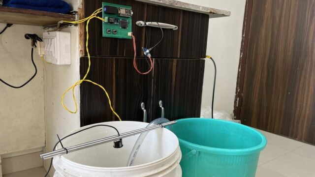
Put the ultrasonic sensor on top of the tank and submerge the motor in the water source. For this proposal, you may use Bucket.
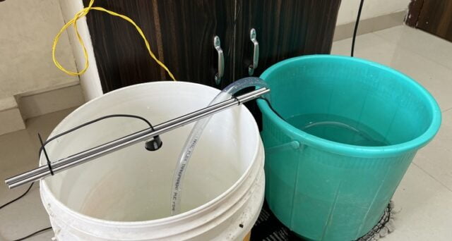
The ESP8266 will establish a connection to the WiFi network. The water level will be shown on the OLED based on the amount of water in the tank.
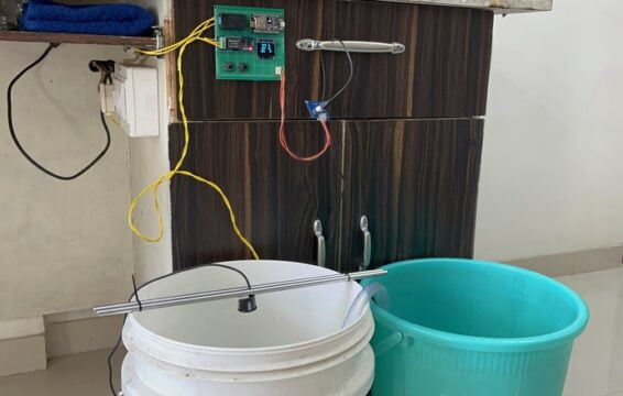
The water level will change from 0 to 100% based on the level of water.
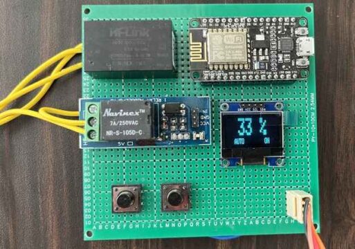
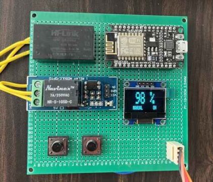
When the water level reaches almost full, the tank will display 100% and the motor will turn off.
The same thing can be observed online on the Blynk application. You can monitor the water level of a tank from any part of the world.
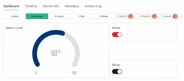
Auto Mode and Manual Mode may be selected from the Blynk Dashboard. You may also force the relay to turn on or off from the dashboard. When the manual mode button is hit, the relay will turn on the motor regardless of the water level.
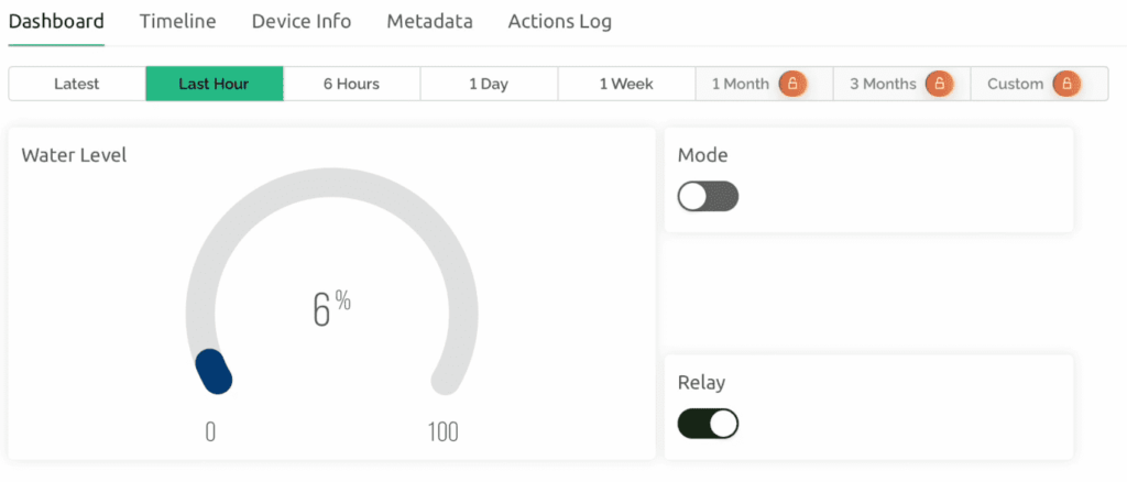
The Blynk Dashboard is accessible for both desktop and mobile applications. Every time it shows the water level in Gague, it also offers the option to turn on the relay from the dashboard or by using the push button on the PCB. Auto and manual modes may be selected in the same manner.
You may also configure the Blynk Dashboard to show a notification when the water level drops below a specified level. The level may be assigned in the code. The default is 20%.
If you like ESP8266, you may also like:
- Getting Started with ESP8266 NodeMCU Board | Complete Guide
- How to Post on Twitter using an ESP8266
- How to Set an ESP8266 NodeMCU Access Point for a Web Server
- How to Send WhatsApp Messages From ESP8266 NodeMCU
We hope you find this tutorial useful. Thanks for reading.


![Arduino UNO R4 WiFi [ABX00087] - Renesas RA4M1 / ESP32-S3 - Wi-Fi, Bluetooth, USB-C, CAN, DAC, OP AMP, Qwiic Connector, 12x8 LED Matrix](https://m.media-amazon.com/images/I/416S910MpBL.jpg)


![Official Arduino Starter Kit [K000007] (English Projects Book) - 12 DIY Projects with All Necessary Electronic Components and Instructions - origianl kit by Arduino from Italy](https://m.media-amazon.com/images/I/51fPv6DsjQL.jpg)


