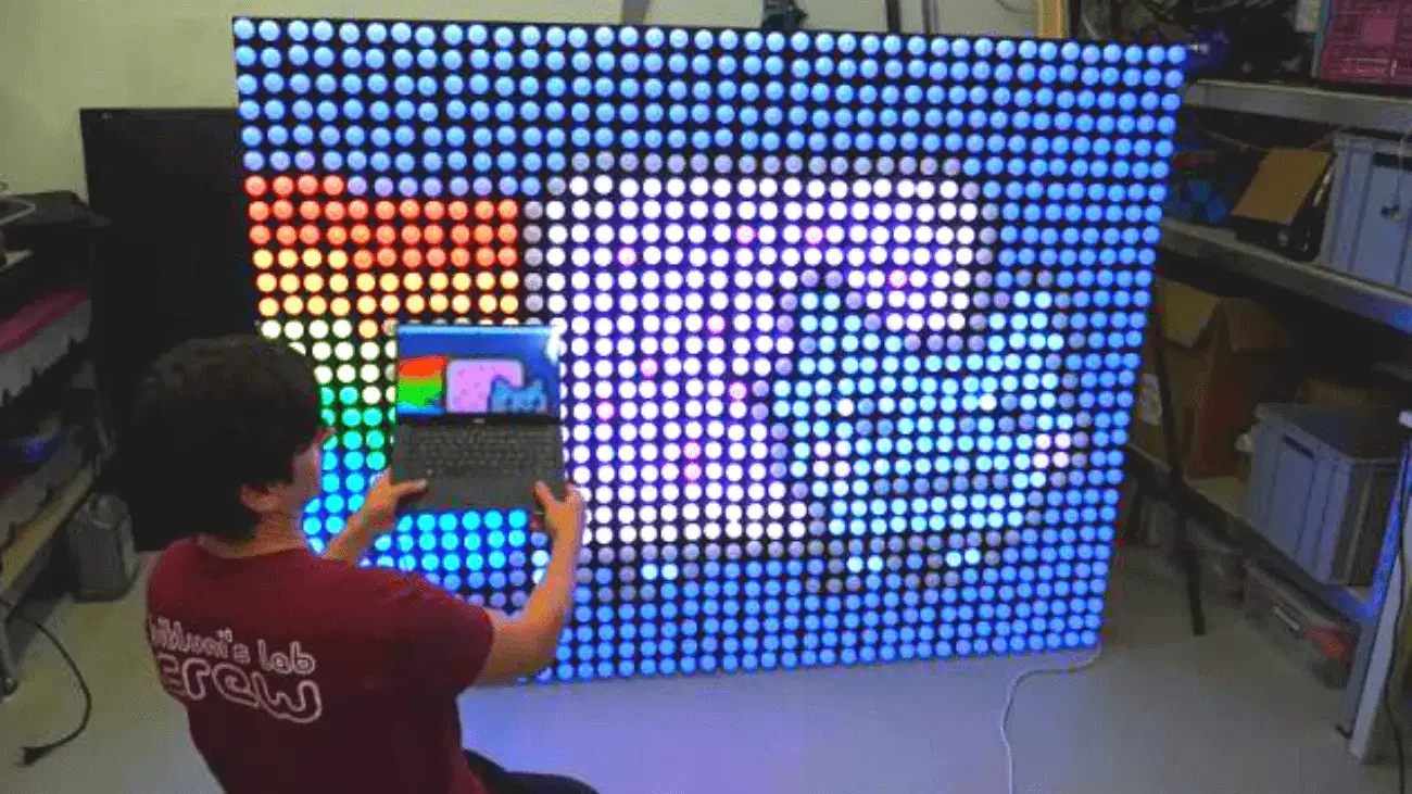
I love LED pixels because they are cheap, simple to control, bright, and so adaptable. But in general, I'm simply in love with clever lighting. Today, we'll build a big LED pixel display that can be hung on the wall of your workplace, either to serve a useful purpose or to look gorgeous.
While connecting the strands of LEDs might be a bit tricky, this project is pretty simple and only takes a short amount of time to complete. The fundamental concept is to arrange strips of LED pixels in a snake pattern on the rear of the photo frame. To help disperse the light, the front will be frosted.
Depending on your demands, the question of which software to use follows. I'll get you started with some sample code and pointers, and we'll revisit the software aspect in a subsequent post when we learn how to pull information like stock prices and notifications onto the display.
Step 1: What do we need

- I chose WS2811 LED pixels since they are cheap and come in a 10-meter strip (sold in two 5-meter reels). If you want a better resolution, you may also get double-density strips with 60 LEDs per meter.
- 5V/10A power supply The model I used has screw connections for a 240V AC input. Purchase an enclosed model if you want maximum safety.
- Arduino UNO REV3.
- I used the offcuts from an old computer power supply, which had several lengths of thick wire.
- 50 cm x 50 cm Ikea RIBBA Deep Photo Frame.
- White paint and glass frosting spray.
Pixel LED Effects Download Pack: 7000 Effects
Under $100 should be the total cost. In terms of equipment, you'll also need:
- Wire stripper
- Hot glue gun
- Knife or scissors
- Soldering iron and solder
Make sure to read our Electronics Skills for Beginners guide first!
Step 2: Do the Calculation

If you buy the same 50 cm x 50 cm Ikea photo frame and LED strands that I did, you should be able to fit 15 strands of 15 lights. Yet nothing is preventing you from using a different-sized frame. I wanted the pixels on the display to be around one-inch square since each LED is spaced about an inch apart—yes, that's one DPI. not quite Retina graphics.
On the frame backing, do the calculation and draw some guidelines. Measure again and check again. When it came time to stick everything down, I realized I could only fit 14 strands of 15 LEDs, so I must have left a small difference between the lines. In any case, modifying the software to accommodate different numbers of pixels with varying row lengths and rows is simple. Cut your LEDs to the proper lengths now. Sadly, I discovered that the soldered connections on one of my reels perfectly lined up with 15 pixels per strand, thus I had to de-solder them. On the plus side, they were pre-soldered back in the day.
Step 3: Frost the Glass

I decided to put some simple glass frosting spray on both sides to help disperse the light from the LEDs. Try to spray as evenly as you can, and do this outside since the fumes are hazardous. After it has dried, the frosting is surprisingly durable, but you must first make sure it is well coated and prevent scratches at all costs.
Spray the back of the photo frame white while you're outdoors to reflect the LED light. The white cardboard photo frame will not be used. For the power and signal wires, trim one corner.
Step 4: Connect the LEDs to the Board

Make use of super glue or a strong adhesive. A hot glue gun is much worse for this when both sides are non-porous; I tried double-sided tape, but it slipped off after a few weeks. If you've purchased strands that are encased in a rubber container, the exact positioning shouldn't be too important since they may move around freely inside it for repositioning.
Keep in mind that each strand of the signal has a specific orientation and will snake around from start to finish. Lay the first strand with the arrow pointing right, then the next strand with the arrow pointing left, and so on. Before you glue them down, double-check this!
Read More: How to Connect LED Light Strips to Arduino: The Ultimate Guide
Step 5: Soldering

Three somewhat different wire lengths will be needed to connect each strand. In each instance, you will be connecting the inner two pads with the shortest wire length, followed by the middle two, and finally the outer two with the longest wire length. Depending on which side of the frame you're working on, the inner pad will switch between the +5V line and the GND line.
Pixel LED Effects Download for LEDEdit
Make sure the wire and the pads are already soldered. This is the project's longest phase, but you must take your time and double-check that you're connecting the right lines.
Step 6: Secure all Strands

Lastly, if you've been moving about the board a lot, you could discover that the first strand has come loose if you've been using the power and input wires that arrived connected to your strand. I chose to thread this portion through a white cable tie after drilling two tiny holes in it. Use this for fastening all the strands at both ends if you're having trouble sourcing strong glue.
Step 7: Wiring Test

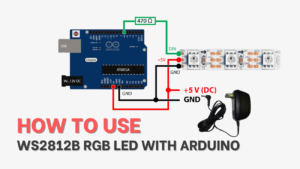
The wiring is simple: Arduino pin 6 is used as the signal power supply to operate the LEDs, while the 5V power coming into the LEDs should come directly from your external power supply. The strand, your Arduino, and the power supply wire should all be connected via a single ground wire. While using USB, do not try to power the strand directly from your Arduino or connect the 5V power strand directly to the Arduino (as it will be to upload the test code).
Download and add the Adafruit NeoPixel library to your Arduino libraries folder, then start the Arduino. Use the sample strand test code supplied in the library to run an initial strand test. Change the number of LEDs in the first parameter of the following line (from 60 to however many):
Adafruit_NeoPixel strip = Adafruit_NeoPixel(60, PIN, NEO_GRB + NEO_KHZ800);Check it right away and unplug the wiring if the animation stops at a particular row. Either the strand is facing the wrong way, the wires are crossed, or you soldered the +5V to the GND by mistake.
Step 8: Place into the Frame

I started by using the hot glue gun to seal the glass to the frame since I'm using a deeper recess than the frame was intended to support. I placed a few short strips of rubber packing around the outside border of the frame to provide the necessary depth before reinstalling the LEDs. I used the hot glue gun once again to seal everything in place after a last test of the LEDs.
To make room for the thick wire, you may also want to make a little incision in the corner of the frame.
That's all in terms of building the display itself; however, you'll ultimately want to conceal the power supply and Arduino in a project box. The remainder is up to the software.
Glediator
Glediator from SolderLab.de is the king of LED matrix control, capable of driving up to 512 WS2812 NeoPixels at 24 frames per second, making it ideal for parties or usage in a professional club setting. You can add GIFs (yeah, Nyan Cat, I'm looking at you) and create live or pre-recorded mixes of LED animations. It also has a fader to smoothly transition between animations, exactly like DJ software.
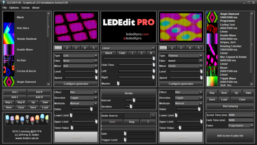
Make sure the signal connection is connected to pin 6 on your Arduino UNO to start using Glediator. Remember to adjust the variable that indicates the number of LEDs you have.
Change the matrix size and output while Glediator is operating by using the settings menu. If your layout is different, adjust the pixel order, but unfortunately, there isn't much instruction for this step, so it's basically trial and error. Try a different setting if the output doesn't match what is seen on the screen. HS_BL, which I suspect stands for “horizontal snake, starting bottom left,” worked for me.

Glediator is a pro-level app, so although I may discuss it in the future, for the time being, I'll let you explore the user interface and experiment. Try loading different animations on the left and right sides, then sliding the fader between the two. Alternatively, you can locate a pre-made playlist of sequences on the far right, as shown in the example video above.
Adafruit NeoMatrix and GFX Library
For working with these types of pixel matrices, Adafruit has created a stunningly useful library. The first is the Adafruit GFX library, which was first created for working with TFT and LCD displays; the NeoMatrix library is a tweak to this that makes all the functions work with NeoPixel LED matrices. After your matrix is created, a vast array of simple functions, such as text output or bitmap sprite display, become available.
You'll find this sample code useful if you make the project exactly as I did. This is the most important part of the code:
#define XSIZE 15
#define YSIZE 14
#define PIN 6
Adafruit_NeoMatrix matrix = Adafruit_NeoMatrix(XSIZE, YSIZE, PIN,
NEO_MATRIX_BOTTOM + NEO_MATRIX_LEFT +
NEO_MATRIX_ROWS + NEO_MATRIX_ZIGZAG,
NEO_GRB + NEO_KHZ800);
The first few lines should speak for themselves. The bottom three tell the graphics library about the layout; in this case, my first pixel is located in the “bottom left“, and it's arranged in rows, with the rows following a zigzag pattern. Check the library documentation if you've oriented it differently.
I've defined a few sprites in the code already (though only the smiley face is used). To create your own sprites, you'll find an Img2Code Java application within the GFX library download.

You should be able to experiment with my sample code and load your own photos for the time being. In a later post, we'll look at using the library to display useful information like stock prices or Twitter streams.
This concludes the tutorial. You've made a massive LED display; now it's only a matter of figuring out what to do with it. Using the remaining LEDs, think of creating a little lightning-cloud lamp.
And if you want to make your PC sparkle with programmable LEDs, here are several ways to do that.
