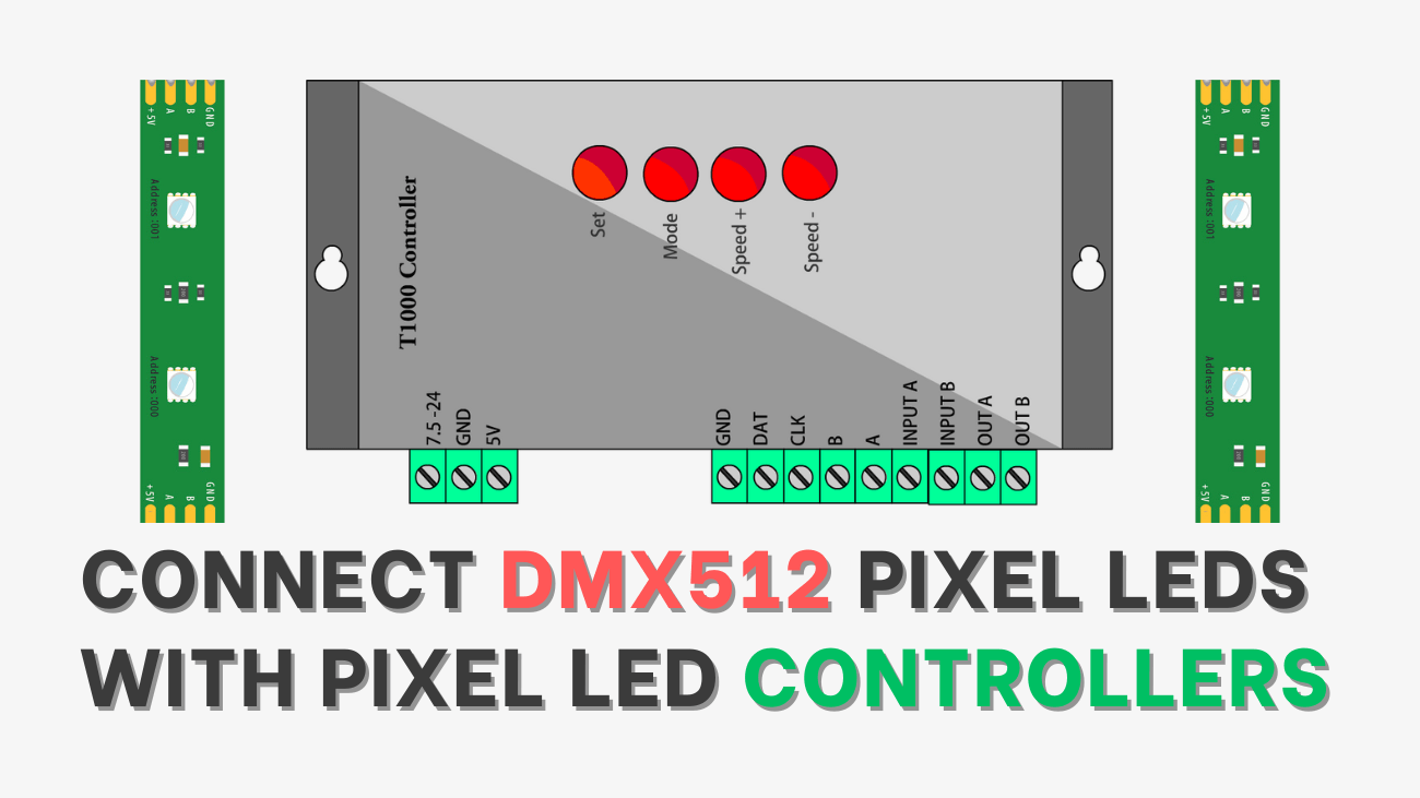
In this tutorial, I will show you how to connect DMX512 pixel LEDs with T-1000S pixel LED controllers and pixel LED wiring diagrams.
Digital multiplexing is a communication protocol used to remotely control lighting dimmers and intelligent devices. DMX is an asynchronous serial digital data protocol. It’s designed to provide a common communications standard between these lighting devices. So that different devices from different manufacturers can work together.
The number 512 after the DMX refers to the number of control channels used on one network segment of devices. In a simple dimming system, one channel controls the intensity of one dimmer. A single intelligent device may require several channels to control its various parameters.
The DMX 512 protocol is based on Standard 485 or RS-485 (EIA/TIA-485 standard), which uses asynchronous, differential data transmission. This standard supports 32 devices on one network at a distance of up to 4000 feet. One device functions as the master (the DMX controller) on a network, while the rest function as slaves (dimmers, intelligent fixtures, etc.). Only the master transmits over the network, and all slaves receive the same data.
Pixel LED Effects Download Pack: 7000 Effects
DMX512 Addressing

The DMX control device will broadcast up to 512 channels. The decoder must be set to the desired channel to control the connected light. This is usually accomplished by setting up the address using a DIP switch or LED/LCD. This desired ‘channel’ is commonly known as the DMX address. If your pixel LED controller doesn't support DMX address writing, you can use a DMX address writer to set the addresses of pixel LED units.
DMX512 Data

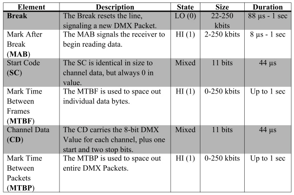
DMX 512 data is transmitted at 250 kHz, meaning that 250,000 per second and 0s (at a maximum) can be sent each second. Each bit is measured in 4-microsecond (s) intervals. For the receiving device to correctly interpret the data, it must be sent in a particular sequence. A single transmission (DMX packet) includes synchronizing elements and channel data for up to 512 channels. The following table describes each element of the DMX packet, including its line state, size, and duration.
DMX512 in Pixel LED Controllers
Most of the pixel LED controllers available today support the DMX512 protocol because there are pixel LED drive ICs that use the DMX512 protocol to communicate. Different pixel LED controller manufacturers use different ports and labels for DMX512 connections.
Here are the most common pixel LED wiring diagrams that use the DMX512 protocol. Pixel LED controllers also use the DMX512 communication protocol to communicate with other controllers when networked together (a cascade system).
In this article, let's look at how to connect pixel LEDs that use the DMX512 protocol with pixel LED controllers like the T-1000S controller.
Download Effects: Pixel LED Effects Download for LEDEdit, NeonPlay, Jinx, and More
Pixel LED Chips That Use DMX512
- UCS512
- UCS512D
- UCS512-F
- UCS512C3
- UCS512B3
- WS2821
- DMX512A
- DMX512AP-N
- TM512C4
- TM512AC
- TM512AS
- SM16512
- SM17500
- SM17512
- SM17522
- GS8512
- QED512P
Pixel LED Controllers That Support DMX512
Wiring of DMX512 Chip to Controller
Here are some of the wiring diagrams of pixel LED strips or strings that use the DMX512 protocol with pixel LED controllers.
Pixel LED Effects Download for LEDEdit
DMX512 Pixel LED Wiring Diagram 1
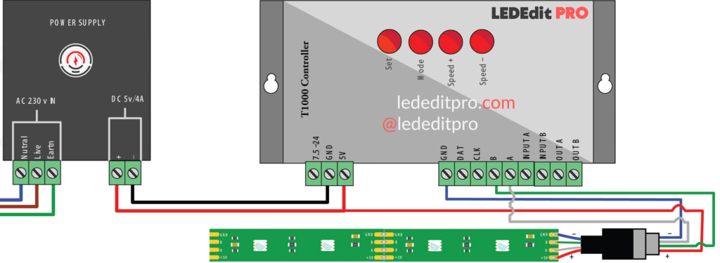
In this diagram, the pixel LED controller's data ground connects to the ground of the DMX pixel LED strip. The A and B outputs of the pixel LED controller connect to the A and B inputs of the DMX pixel LED strip, respectively. The +5-volt line of the power supply connects to both the pixel LED controller and the DMX512 pixel LED strip.
Note: Depending on the manufacturer, the colors of the wires and A and B labels may differ. If the Pixel LED strip or string is not working, please swap the A and B connections of the Pixel LED controller.
DMX512 Pixel LED Wiring Diagram 2
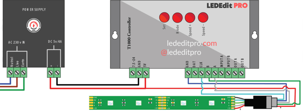
In this diagram, the pixel LED controller's data ground connects to the ground of the DMX pixel LED strip. The A and B outputs of the pixel LED controller connect to the D+ and D- inputs of the DMX512 pixel LED strip, respectively. The +5-volt line of the power supply connects to both the pixel LED controller and the DMX512 pixel LED strip.
Note: Depending on the manufacturer, the colors of the wires and A and B labels may differ. If the Pixel LED strip or string is not working, please swap the A and B connections of the Pixel LED controller.
Download Effects: Pixel LED Effects Download TOL format for LEDEdit Software
UCS512C4 / SM16512 / TM512C4 / TM512A Pixel LED Wiring Diagram 1
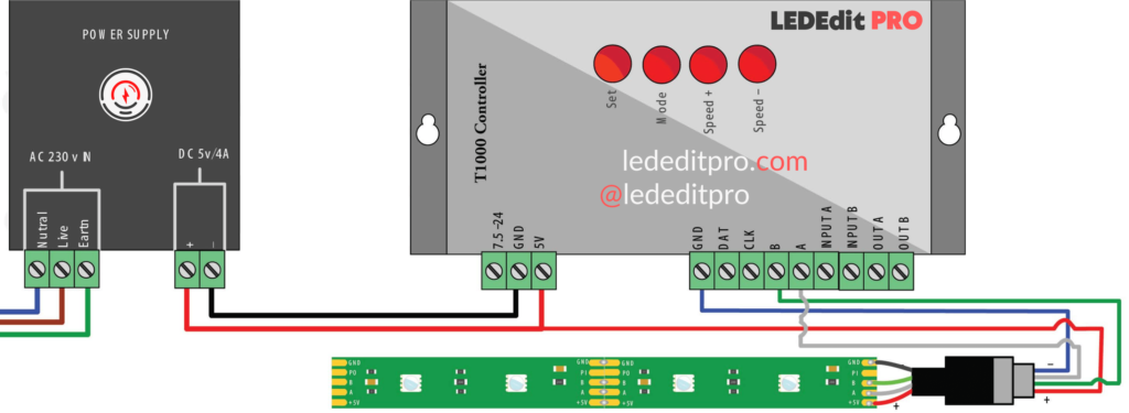
In this diagram, the pixel LED controller's data ground connects to the ground of the UCS512C4 DMX pixel LED strip. The A and B outputs of the pixel LED controller connect to the A and B inputs of the UCS512 pixel LED strip, respectively. The +5-volt line of the power supply connects to both the pixel LED controller and the UCS512 pixel LED strip. The P input of the pixel LED strip is for channel selection; you don't have to connect to anything. If this wiring doesn't work, please check the next diagram.
Note: Depending on the manufacturer, the colors of the wires and A and B labels may differ. If the Pixel LED strip or string is not working, please swap the A and B connections of the Pixel LED controller.
UCS512C4 / SM16512 / TM512A / TM512C4 Pixel LED Wiring Diagram 2
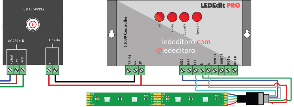
In this diagram, the pixel LED controller's data ground connects to the ground of the UCS512C4/SM16512/TM512AC DMX pixel LED strip. The A and B outputs of the pixel LED controller connect to the A and B inputs of the UCS512 pixel LED strip, respectively. The CLK (clock) terminal of the pixel LED controller connects to the PI (port input) of the UCS512 pixel LED strip. In this case, the clock line of the controller generates the channel data. The +5-volt line of the power supply connects to both the pixel LED controller and the UCS512 pixel LED strip.
Note: Depending on the manufacturer, the colors of the wires and A and B labels may differ. If the pixel LED strip or string is not working, please swap the A and B connections of the pixel LED controller.
WS2821 DMX Pixel LED Wiring Diagram
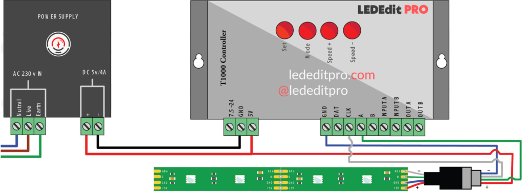
In this diagram, the pixel LED controller's ground connects to the GND (ground) of the DMX pixel LED strip. The A output of the pixel LED controller connects to the D input (data) of the WS2811 pixel LED strip. The CLK (clock) line of the pixel LED controller connects to the Adi (address in) of the WS2821 DMX pixel LED strip. The +5-volt line of the power supply connects to both the pixel LED controller and the DMX512 pixel LED strip.
Note: Depending on the manufacturer, the colors of the wires and A and B labels may differ. If the pixel LED strip or string is not working, please connect the wire that connects to the A terminal to the B terminal of the pixel LED controller.
UCS512B3 / CS512A Pixel LED Wiring Diagram
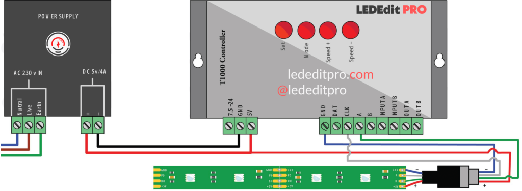
In this diagram, the pixel LED controller's data ground connects to the ground of the UCS512B3 or CS512A1 DMX pixel LED strip. The A output of the pixel LED controller connects to the DI (data in) input of the UCS512B3 or CS512A1 pixel LED strip. The CLK (clock) terminal of the pixel LED controller connects to the Pi (port input) of the UCS512B3 pixel LED strip. In this case, the clock line of the controller generates the channel data. The +5-volt line of the power supply connects to both the pixel LED controller and the UCS512B3/CS512A1 pixel LED strip.
Note: Depending on the manufacturer, the colors of the wires and A and B labels may differ. If the pixel LED strip or string is not working, please connect the wire that connects to the A terminal to the B terminal of the pixel LED controller.
DMX512AP-N / WS2821 Pixel LED Wiring Diagram 2
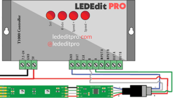
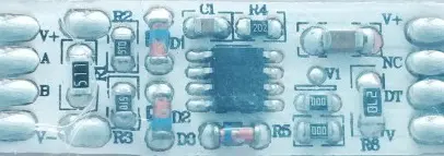
As you can see in the image, to connect the pixel LED controller to the DMX512AP-N or WS2821 pixel LED strip, a DMX converter is being used. The A and B outputs of the pixel LED controller connect to the A and B inputs of the DMX converter, and the +5 and GND of the DMX converter connect to the power supply's +5 volt and GND outputs. The D output of the DMX converter connects to the D (data) of the DMX512AP-N pixel LED strip, and the NC output of the converter connects to the Adi (Address In) of the pixel LED strip. The +5 volts and GND of the pixel LED strip are connected to the +5 volts and GND of the converter. However, if you are using this method, you have to use a DMX address writer to write the address of the pixel LED strip's chips.
Note: Depending on the manufacturer, the colors of the wires and A and B labels may differ. If the pixel led strip or string is not working, please swap the wires that connect to the A and B terminals of the pixel led controller.
